SECTION 39: CONTROL SYSTEM
Jump to navigation
Jump to search
Build Instruction Updates
- 11/05/22 39_10.pdf
Check for more recent updates here
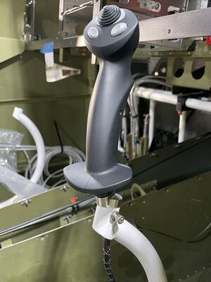
Modifications to avoid the grip hitting the panel
Stick Grips
- See Stick Grips
Page 39-2
- Step 3: If you have issues printing the document to scale, try printing this file instead:Pushrodholes.pdf
- Note: HP laser printer drivers on Mac laptops may not print at the needed 1:1 scale, no matter what software you use or what you do in the print settings. Exact same file, printer and Adobe Reader are able to print at 1:1 scale on a Windows laptop. There might be an issue on Macs.
- Hint for Onshape users: You can import a pdf page via Inkscape. Import the pdf page in Inkscape and save it out as dxf v14 file. Import that dxf file into Onshape. Start a new sketch. Add the dxf drawing to the sketch. Take a known distance between two points and call out a dimension between them. It will show the distance as it imported the drawing. You can now override that distance to the known distance and the whole dxf is now at scale. You can now overlay your own drawing while the endpoints will snap to the dxf points. Next, create a drawing within Onshape and add the sketch. You can then export that drawing back to a pdf and the scale is correct.
Page 39-3
- Step 2: You need two holes that are opposed to each other and aligned so you can get a straight safety wire through later.
- Step 4: One way to prime the inside of the tubes is to hang them off the ceiling dangling 2 inches above the ground. Then inserting a bow tie of paper towel that acts as a plug with a wire that allows you to pull it out the bottom. Pull it down so you can pour an inch of primer into the tube without spilling out the holes. Then slowly pull down the plug. Catch the paint running out the bottom once the plug is coming out.
- Step 5: The long rod end bearing is nominally 2.312" from bolt end to hole and the short one is 1.375. The rod ends are sticking out 0.75", therefore the threads should engage 0.390" into the rod end fitting on both ends to yield a hole to hole length of 37 13/32. Taping the jam nuts into the 0.39 position will make it easy to do the initial thread insertion. 52% of the short and 26% of the long rod end bearing thread is engaged with the rod end fitting.
Math: (33 + 1.5 + 2.312 + 1.375 - 37.40625)/2=0.39
Page 39-4
- Step 5: Similar to F-1089, the F-1090 thread engagement can be calculated to 0.718".
Page 39-5
- Step 1: Similar to F-1089, the F-1064 thread engagement can be calculated to 0.687".
- Step 2: Similar to F-1089, the F-1065 thread engagement can be calculated to 0.5".
- Step 3: You thread in the front tube first (with the long rod end bearing first), then the rear tube.
Page 39-7
- Step 4: Don't force washers in and don't have play before tightening the bolt. Consider adding 1/64th thick washers. Make sure that after tightening the second side down, no binding can be felt from the bearings that might have taken on side load.
Consider using a drilled bolt and a castellated nut / cotter pin.
Page 39-8
- Step 1: The bearing surface is between the outer side of the bushing and the inside of the base pivot tube. Therefore, it doesn't matter if the bolt sits tight inside the bushing, it's actually good if it sits tight. Be careful removing burrs from the inside of the base pivot tube. The play between the bushing and the base pivot tube must be minimal. Consider adding grease to the outside of the brass bushing (e.g. Permatex Anti-Seize or Aeroshell #22 which is also later needed for the wheel bearings).
- Step 3: Insert the bolts that hold the aileron pushrods from front to back to avoid binding with the F-1033 Control Column Mounts.
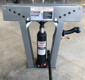
If you install an Aerosport 310 panel, you probably will have interference between the grip and the panel. Also, if you opted to let the elevator travel reach its maximum angle of 25 degrees down (only 20 down is required, see first flight section), even the stock panel might interfere with a grip (especially the Tosten 8 button since it is tilted forward). The WD-1011-L/R Control Stick Bases have large tolerances concerning the angle the control stick has versus the WD-1010 Control column. If the angle is more forward, your stick will interfere more with the panel. If the angle is more rearwards, the bottom aileron pushrod bolts of the Control Stick Base will interfere with the F-1033-L/R Control Column Mounts. Also the aileron center pushrod will interfere with the tunnel side wall cutouts. Consider asking Vans for an exchange of the bases if they are too far off. The angle between the control column brass bearing and the exiting control stick should be 20 degrees up. The angle between the control column and the centerline of the bracket that holds the aileron pushrods should be 90 degrees (brass bearing and aileron pushrod bolts should be parallel).- To fix the grip interference, a lot of builders bend the control stick with e.g. a hydraulic HF tube bender (don't forget to fill the tube with sand). However, then, the elevator all up position might interfere with the pilot / passenger with the seats in the front 3 notches, especially, if you opted to let the elevator travel reach its maximum angle of 30 degrees up (only 25 up is required). See also this FB thread from 2021 and this FB thread from 2023.
- Tosten supplies a 5 degree tilt adapter on request that moves the top of the stick about 0.5 inches back.
- If you want to reach larger tilt angles, see this [1] FB thread that refers to a 22.7 degree adapter design that yields 2.5 inches.
- Some have opted to lengthen the pushrod setup to move the stick aft. This may require longer rod end bearings as the stock thread engagement is only about 1/2 inch. This may introduce binding between the aileron pushrod bolts and the F-1033 Control Column Mounts which needs shaving. See this FB thread.. This may also introduce binding between the central aileron pushrod and the elevator pushrod.
- To fix the grip interference, a lot of builders bend the control stick with e.g. a hydraulic HF tube bender (don't forget to fill the tube with sand). However, then, the elevator all up position might interfere with the pilot / passenger with the seats in the front 3 notches, especially, if you opted to let the elevator travel reach its maximum angle of 30 degrees up (only 25 up is required). See also this FB thread from 2021 and this FB thread from 2023.

