SECTION 38: RUDDER PEDALS & BRAKE SYSTEM
Jump to navigation
Jump to search
Build Instruction Updates
- 11/15/04 38_10.pdf
Check for more recent updates here
Page 38-3
Step 2
- Consider using an improved break pedal hinge mechanism using a single axis and bronze bushings. See Brakes_/_Wheels, chapter "Improvements to Brake Pedal and stock Master Cylinder".
Step 3
- Since the master cylinder rotates a bit at the fastener ends, make the nuts only hand tight and then losen them 1/4 turn, then put the cotter pin in.
Page 38-4
Step 5
- The manual only shows how to install the pedals in the forward position. It is also possible to install the pedals one hole further back to accommodate pilots with shorter legs. One can adjust the seat forwards and backwards in the RV-10 but that does not change the distance between the control stick and the pedals. Page 38-10, step 1 shows how to tailor the rudder cable link for the two rudder pedal mounting options which shows it is supported.
See also Bob's log entry: Relocate Rudder Pedals
See also this FB thread. - The QuickBuild fuselage might have the holes in the longeron for the Bearing Block Mount Plate F-1039B drilled a little bit off spec which might need adjustment with a round file or match drilling.
page 38-5
Step 2
- It might be necessary to sand the upper surface of the upper half of the F-6115 block a bit to make it fit less snug underneath the rudder pedal brace.
Step 3
- If the ruder pedals have too much friction after tightening down the center bearing block, add a washer on each side in-between the halves to compensate for the saw blade thickness. See also this VAF thread
Page 38-8
Step 2
- Before inserting the rudder cable consider adding a rudder cable fairing to your build. Avery makes a suitable fairing and is available from e.g. Aircraft Spruce. Draw lines 1 inch above and below the exit hole.
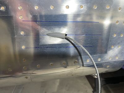
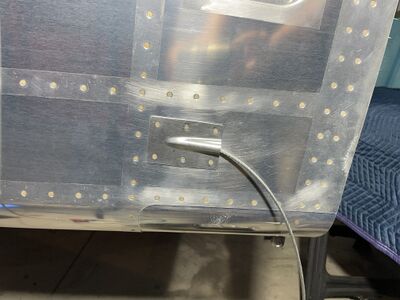
See also this Wiki page for variants of how to shape and mount the fairing: Rudder_Cable_Fairings. - It's hard to install the Adel-clamp which holds the sleeve at the tail end. Best to first get just the screw test threaded into the nut plate and backed out. Then capture just the cable with the adel clamp, hold the adel clamp closed with a temporary safety wire or a Hemostat and get the bolt in a few threads deep. Then remove the safety wire or Hemostat and capture and position the cable sleeve. Lastly tighten the bolt.


Page 38-10
Step 1
- Since the links are used in pairs, drill the holes in pairs so the bolt holes align
- The links are steel, best to be drilled with a drill press and the links clamped in a drill press vise sitting on top of a piece of wood that is slightly narrower. The steel is soft, the holes can be drilled in a single step with a #12 bit.
- Some builders make the left and right link different length so the pedals are neutral when the rudder is straight. This requires installing the rudder to assess the needed length.
Step 6
- The rudder cable is much thicker than the nylon slot. The slot is also square and the cable round. It helps to bevel the slot edges with a Dremel router.