SECTION 11: EMPENNAGE ATTACH
Build Instruction Updates
- 10/05/21 11_10.pdf
Check for more recent updates here
Note: there are a lot separate steps in this section that require priming. Especially if you are using epoxy primer and a spray gun, you may want to read ahead. For example, when/if you prime on 11-5 Step 3, or 11-6 Step 4 (pushrod) you may want to jump ahead and do the rest of the fabrication, deburring, and priming:
- Page 11-8 Steps 1 through 7
- Page 11-9 Step 1
- Section 12, Page 12-6, F-1094A Empennage Gap Covers (deburr and prime inside surface)
Page 11-2

Tool to screw in the rod end bearings. The outer ring is a cut-off fitting.
And a link to Sam Buchanan's tool fabrication: http://home.hiwaay.net/~sbuc/journal/odd-ends.html#bearing%20tool
Looks like the picture above (not my post) uses a drilled hole at the top of the tool which is probably better since it can be adjusted in tight places...
Step 3: I found this nearly impossible to do without a few tricks. Even then it is best to get at least one helper.
- The brackets on the elevators that you are attaching to in Detail B tend to be a bit too narrow.
- Make two small wooden wedges that you can insert in there to spread the bracket a bit -- I used the end of the wedges I cut out for the trim tab holders.
- Ruin two AN3-10A bolts by grinding down the end to make it have a smooth and narrow end.
- Insert both wedges, then insert the bearings into the brackets. Insert these modified bolts to attach the elevator. You may need to tilt the elevator far up or down and use needlenose pliers to get the bolt in there.
- Nuts should still thread onto the end of these modified bolts -- that is good for now. Obviously, you'll need to use unmodified bolts later for final assembly. I actually didn't install any nut (or washer) for most of the work in this section.
- Note that the sentence in this section that refers to Detail C doesn't actually apply until you attach both elevators ("Not completely filling the gap between the elevator horn and the VA-146..."). That sentence is letting you know that it is important to fill the gap complete (I found it confusing).
Step 4: I used two clamps per side instead of duct tape.
Page 11-3
Step 5: Now this is where you use Detail C from the previous page. Make sure to fill the gaps as much as possible and fully tighten. Make sure the elevators are perfectly even before drilling. You can use flat dental floss to help get the washers in place, and/or Washer Wrenches. It's tough to get two washers in one side without some dental floss.
Again, I used two clamps per side to line the counterweight with he HS.
Page 11-5
Step 3: Because I had to remove the VS and HS later before transporting to my hangar, I did not remove and prime the parts at this stage.
Page 11-6
Step 4: This step details how to mark a template to drill six holes around each end of the control rod. Section 39 (Control System), page 39-4 step 3 has a better method of drilling the rivet holes. In particular, use a center punch to make sure the drill does not wander, and use a drill press if you have one for best accuracy. Rather than cutting up the plans as Vans suggest, take a photocopy and use that.
Page 11-7
When installing bolts in the rod end bearings for the elevators and rudder, I used a set of hemostats w/ some blue tape on the tip to hold the bolts during the install. Worked great to take in/out of the bearings.
Page 11-9
- Step 5: As a starting point, check these drawinging
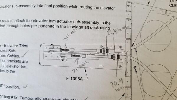
The centered starting values for the trim cable nut positions are not very good and require painful iterations.
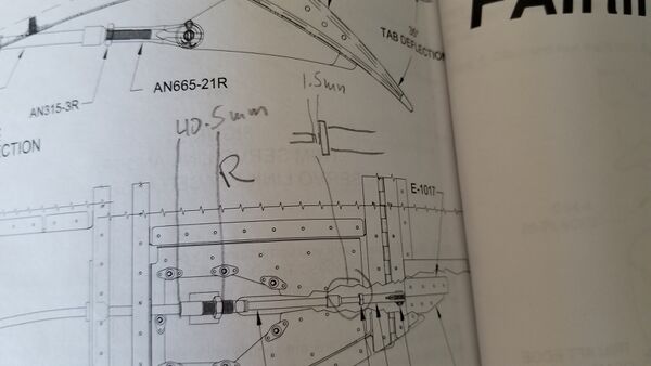
Goal is that both tabs go down 35 degrees, are in sync in neutral and the right tab goes up 25 degrees while the left one stays neutral in all up. - Good right cable starting values:
3 threads exposed at the servo clevis,
21.4 mm from where the green ends at the servo side to the first nut
40.5 mm from where the green ends at the trim tab side to the bracket end
1.5 mm exposed of the threads at the trim tab clevis. - Good left cable values:
7 threads exposed at the servo clevis, 20.9 mm from where the green ends at the servo side to the first nut 42.6 mm from where the green ends at the trim tab side to the bracket end
1 mm exposed of the threads at the trim tab clevis. - Check also this thread on same topic: VAF.
- Be sure to check the position output of the Ray Allen servo early in the process. There was a bad batch of Ray Allen servos where the potentiometer has intermittent output when cold (showing after 5 minutes in a freezer (keep servo in a freezer bag to avoid condensation).

